 2006
2006


The machine room
by Johan Kjellander 2006, 2014
January
Once again I'm starting on a new page for a new year. I'm getting routine on this ! I'm still working with the heating system. All tubing is finished, convectors mounted and only a few hours left to finish the accumulator tank. Meanwhile I have assembled a slideshow as a PDF file that you can download if you wish. It starts back in 1997 with the boathouse and continues until today (updated 2014). The file is big (20Mb) but the pictures are generally in higher resolution than the pictures I have put up on the web so far.
If you have a fast internet connection the slideshow is a good way to get a quick overview of the project. Download the PDF-file here . You are free to use the pictures any way you want but if you send them on to somebody else or show them publicly it would be nice if you mentioned the source.
February
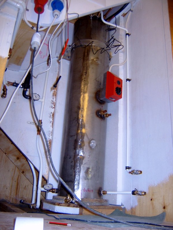
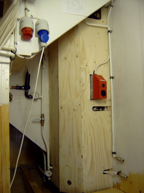
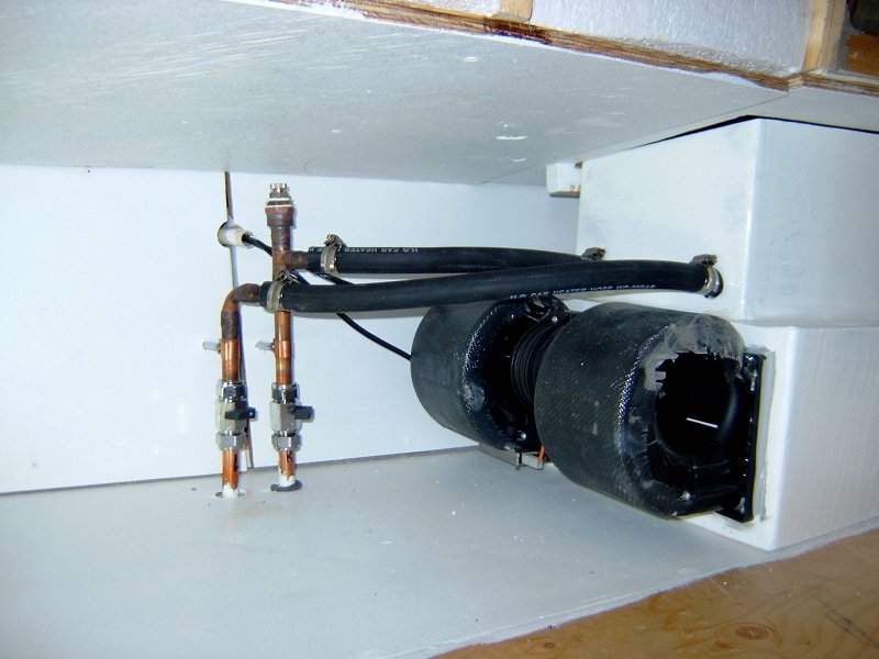
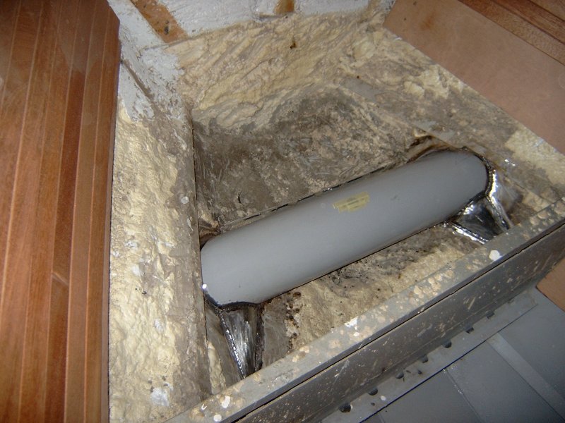
The heating system is finally finished. The tank is connected to the radiator circuit and hot water is circulating. To the left is a picture of the tank in position and the right picture shows how it will look when heat insulation and plywood covering is in place. The pump I'm using is a Swedish Johnsson radial pump with magnetic coupling between the motor and the pump wheel. According to my measurements it draws only 0.3 Amps at 13 volts. However, I made an experiment by adding a 20 Ohm resistor in series and this seems to work just as well. With the resistor the current drops to 0.2 Amps while power decreases about 50%. This lowers the noise level (which is very low anyway) and probably prolongs the lifetime of the pump as well. It also saves electricity by 30% which is good for batteries. So far the only way to heat the water is by electricity. The 3X400 Volt 3 kW heater is more than I need right now with outdoor temperature around -5 centigrade. Currently I have set the thermostat on the heater to 40 degrees and the thermostats on the radiators to 8 degrees. This keeps an even temperature throughout the entire boat. During weekends when I work all day I raise the thermostats on the radiators to 15 degrees which is a good working temperature and enough for paint to dry.
Galvanic corrosion due to currents flowing from the shore ground through the electric heater, the water in the tank, the heat exchanger connected to the motor, the propeller shaft and finally the propeller into the seawater is a big risk ! I therefore decided to separate the 1X230 Volt system from the 3X400 Volt system totally. I have two separate shore inlets, one for each and their ground is not connected to each other inside the boat. This means that I can have the 230 Volt system connected to shore without risk. The 3X400 Volt system can only be used when out of the water or if the connection to the motor is dismounted. I plan to make this as easy as possible.
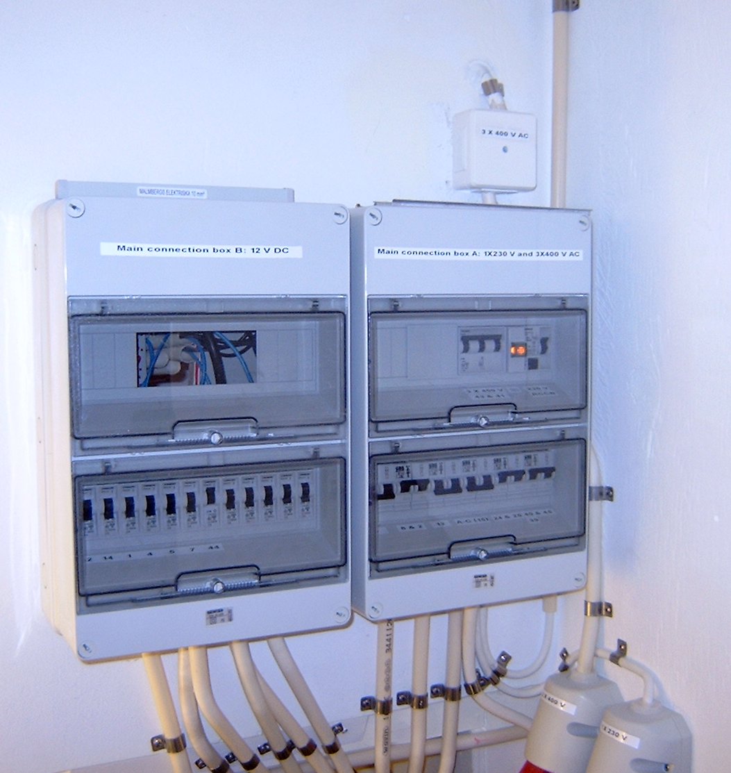
The AC system is now more or less finished so I have started to mark up all fuses etc. with self adhesive plastic labels. I bought a DYMO LabelPOINT 150 printing machine and permanent tape for this. The result is very neat and professional I think. The AC connection box is to the right in this picture while the 12 Volt DC box is to the left.
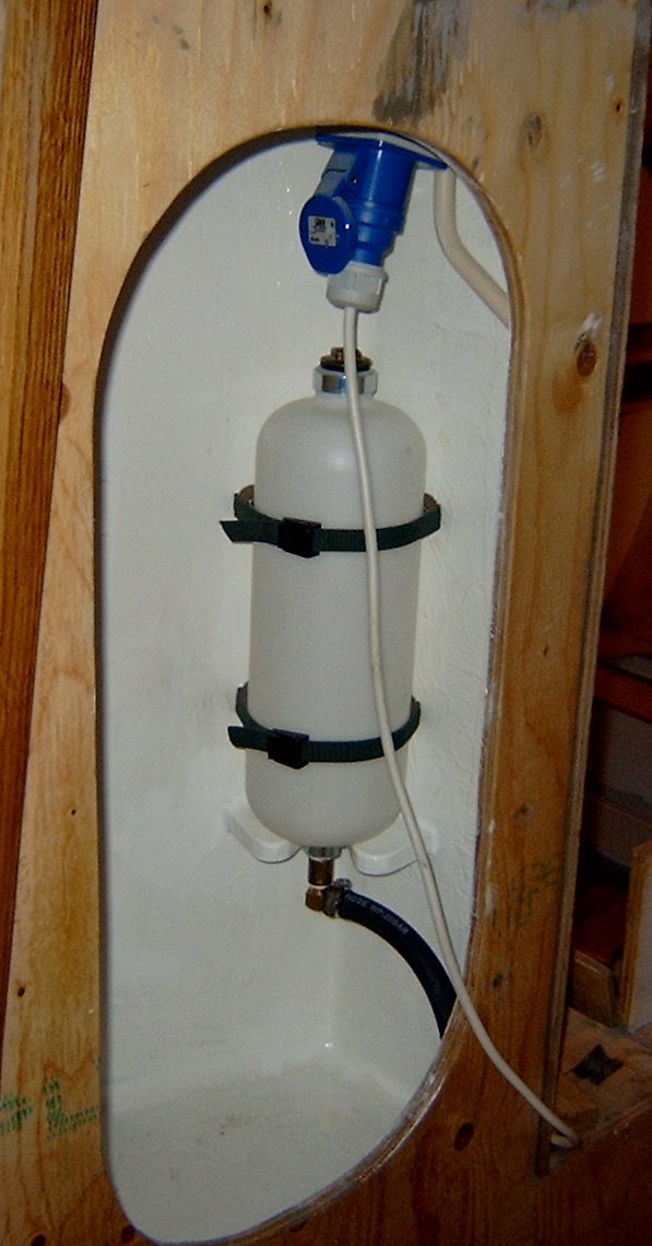
Water expands approx. 5% in volume if you raise the temperature from zero to 100 degrees. To take care of the expansion and create a small over pressure I installed this expansion tank at the highest position possible.
I have also connected my home made defroster unit. It works very well and produces lots of hot air that will keep the windows dry inside.
The plan for the near future is to finish the showers. I need to fix water outlets, greywater tanks with pumps, ventilation etc.
March
Tove and I made a visit to the Stockholm boat exhibition in the beginning of Mars. Tove focused on various equipment for the galley and bathrooms and things like that, while I spent my time in stands showing motors, shafts, tanks and diesel heaters. We also collected a good 20 kg of catalogs. It's a big exhibition with hundreds of stands so it takes some time to cover it. While running around we found a small stand with a man demonstrating a flexible vise named Zyliss. The man made a good show that was very convincing. We stood and watched him work for a while and slowly I started to think about my small workshop that I was planning to have in the machine room. This vise would fit in very well. Said and done, so I ordered one !
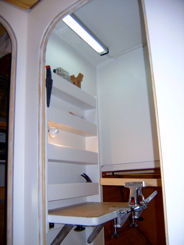
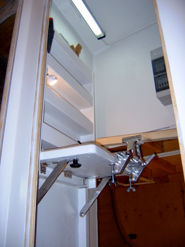
Next I had to design a workbench that would fit in the machine room. It could not be very big and it had to be down folding to give room for other activities when not in use. It also had to be very steady to be able to carry the load from the vise. I bought a 12 volt 13 watt fluorescent lamp to put in the ceiling above the bench and also a 12 volt 10 watt halogen spotlight to light up the workbench area. Above the bench I designed 4 shelves with place for tools etc. Above is the result. When the bench is down folded it takes very little space. With the vise mounted on the bench it gives you many possibilities and feels very steady.
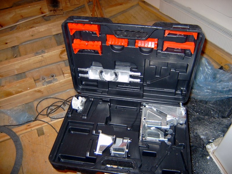
The Zyliss vise comes in a plastic case with a lot of different parts that can be used to fasten almost anything anywhere in any position. You can use it as a vise but also for clamping. It has one part that can be used to fasten an electric drilling machine. You can mount it anywhere as long as you have a flat surface 10-50 millimeters thick. It's easy to carry outside on the dock or into another boat if needed. I also plan to prepare some place on the aft deck where I can put it if I want to. The price during the exhibition was just below 2000:- SEK.
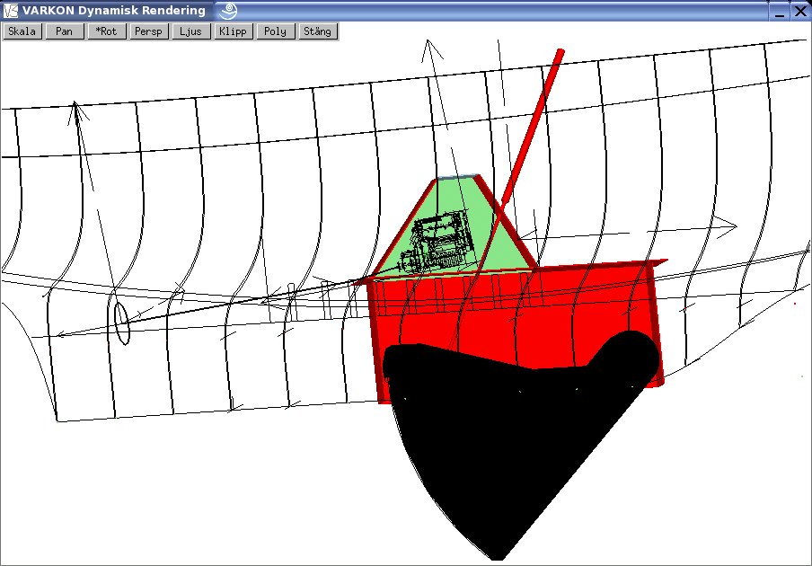
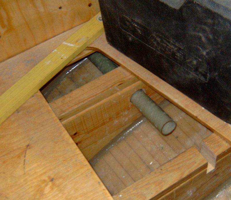
I'm also planning the layout for the rest of the machine room. There will be two motors of approx. 40 hp each, one on each side of the keel box. There will also be a water tank, a septic tank and two fuel tanks. With one water tank already mounted this will give us a total water capacity of 800 liters, a fuel capacity of 600 liters and a septic tank of 250 liters. The propeller shafts will be 30 millimeter in diameter, 2.5 meters long with propellers in the range of 17 inches in diameter. Each shaft will run inside a glass fiber tube that will be bonded into the hull. Inside the boat the shafts will be connected to rubber mounted axial bearings (Aquadrive or similar) and finally connected with the motors by 500 millimeter long shafts with CV joints. Each motor will be enclosed by a sound insulated box to keep the noise down. The ceiling and most of the walls of the machine room will also have sound (and heat) insulation. I plan to use a mineral based material for this which also gives protection against fire. I should end up with a very quiet and safe motor installation I think. Above is a picture from my CAD system that maybe gives you an idea of how the keel, motors and shafts are placed relative to each other. Only one motor is shown in the picture !
May
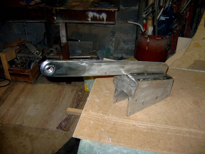
The chainplate for the aft stay is not yet finished. I got hold of some thick stainless metal and made this piece. It will be bolted through a thick wood fastener with 6 bolts 12 millimeter diameter and rest against an oak beam that will spread the forces into the stern and aft deck. I'm still waiting for warmer weather before i bond the wood pieces to the hull.
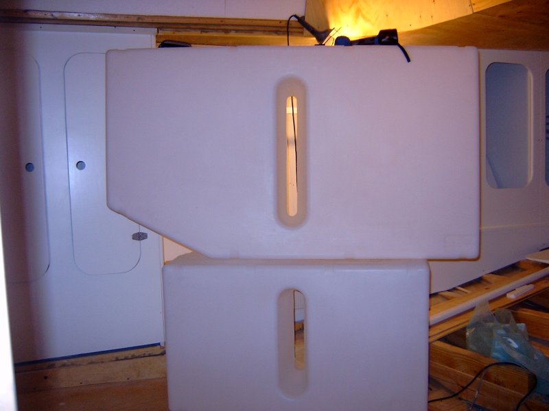
The main job lately however has been planning the machine room layout. It has been difficult to decide where to put the tanks so that it will be possible to reach the motors from all sides. I finally decided to bye 4 plastic tanks from Vetus. They are made from polyethylene and CE-classed for offshore use. The material is transparent so you can easily check how much diesel or water is left and this saves me the cost of electric level indicators. The weight is lower than metal tanks and so is the price. Only drawback is that I have to select from a limited range of sizes and dimensions. Two of them are big (395 liters each) and two of them are smaller (215 liters each). Above is a picture of one of the big tanks resting on top of one of the smaller temporarily placed in the aft cabin.
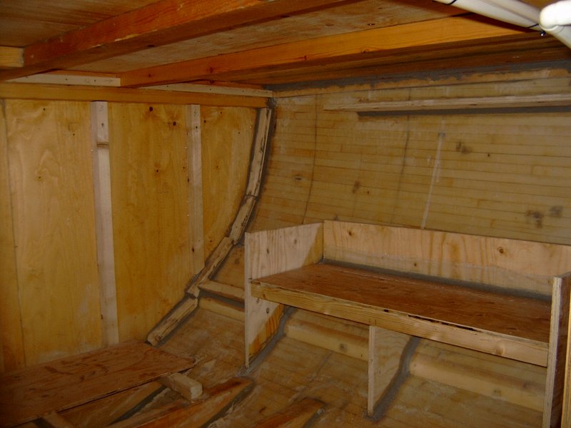
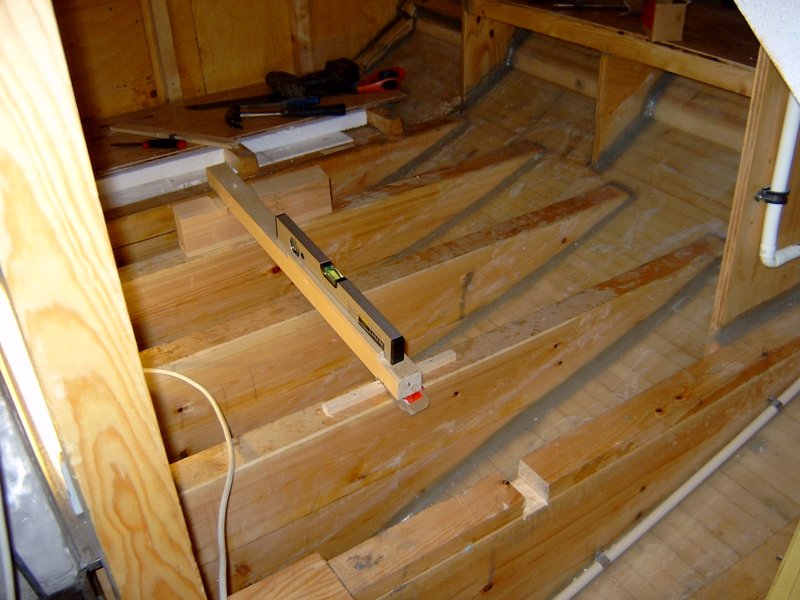
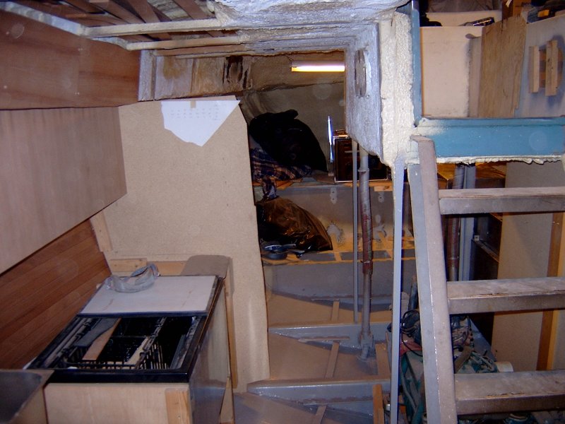
The big tanks will be placed tight against the forward bulkhead of the machine room, in front of the motors. The two small tanks will be placed one on each side of the motors close to the hull. This picture shows the starboard side of the machine room. The shelf on the hull side is for the small tank and the square piece of plywood down to the left is the place for the big tank. The forward bulkhead and the ceiling will be insulated with mineral based heat/noise/fire insulation and covered with Minerit boards. Minerit is fireproof, water resistant and has good noise reduction properties.
June
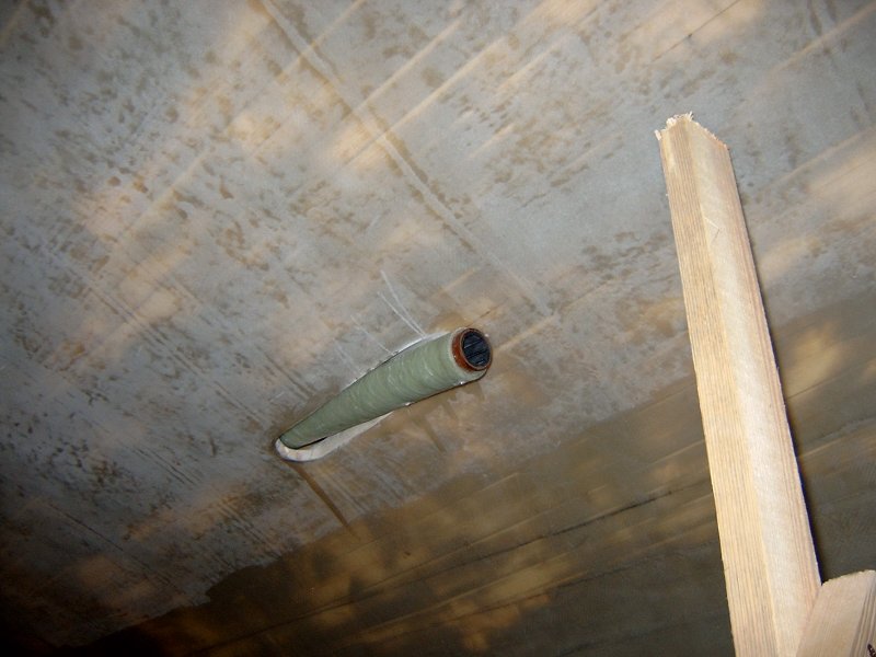
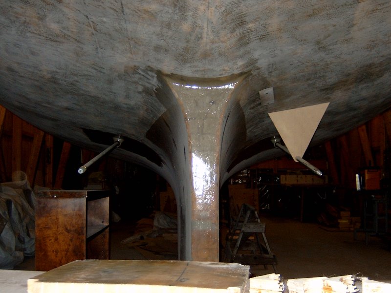
Now it's time for propeller shafts. Two motors means two shafts and they will run in glass fiber tubes bonded to the hull. Above is a picture of the port side tube sticking out through the hull. It ends with a rubber (cutlass) bearing. The shafts will be 30 mm in diameter. Inside the tube endings will be tightened with Mane Craft sealings and the shafts will be connected to Aquadrive bearings.
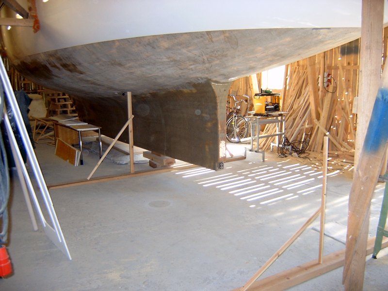
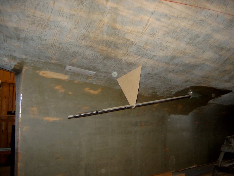
With one shaft, aligning is not an issue, but with two shafts it seems important to make them parallel. So, I mounted my laser inside and measured and measured. Outside I built this construction to take the measures. I did the best I could and if the boat goes in circles I can only blame myself !
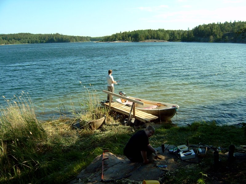
The midsummer holidays were spent in our summer house on Åland. It's a wonderful place close to the water. We spent one day building a new jetty for our fishing boat.
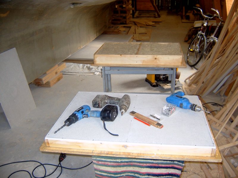
Work with the motor room goes on. The roof and the forward wall will be insulated (heat and sound) and covered with fireproof boards. Here is a picture showing the work with the motor hatches. Insulation is mineral based and the boards are based on a mix of concrete and wood (Minerit). These boards have excellent sound and fire protection properties.
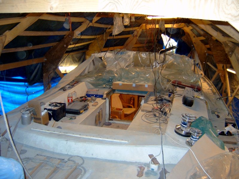
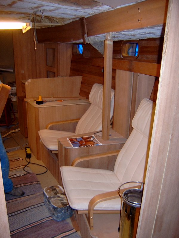
It seems I have many friends building boats. We are inland and 200 km's from the Baltic but the dream lives ! I have some new pictures from a steel boat built by one of my friends. He bought the hull and is finishing the rest himself. Above is a picture showing the deck and to the right is a picture from inside.
He is planning to have a bow thruster. The tube is welded to the hull. To the right is a picture from forward to aft inside. You see the galley to the left, the motor to the right and the aft cabin in the back. The hull is painted outside but there are still many things to finish on deck and inside.
July - September
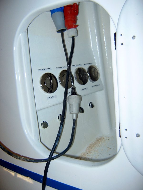
Summer 2006 passed quickly with a lot of small but interesting jobs completed. Bigger jobs like sanding or painting the hull tend to go slower because they are boring. Tank installation is one job that I have written about before. Here is a picture from the outside locker where all 4 tanks are filled. Note the air outlet below each of the tank filling caps.
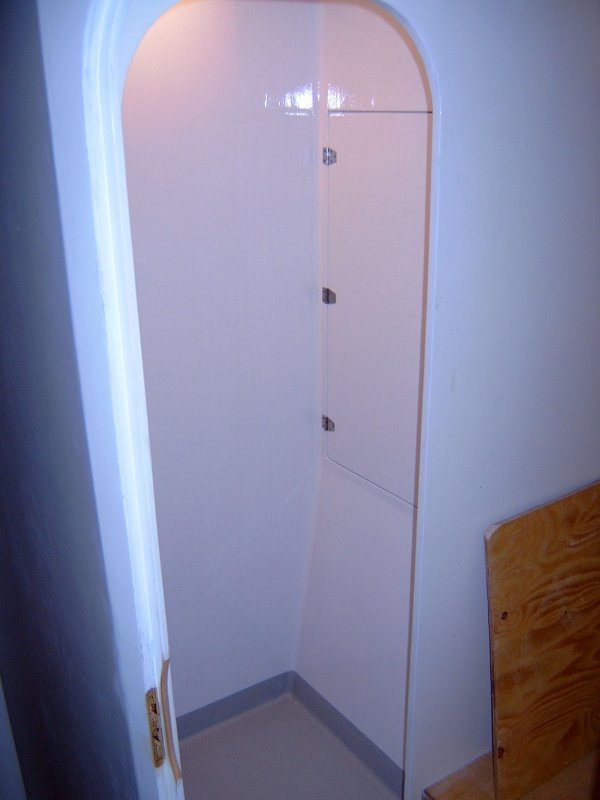
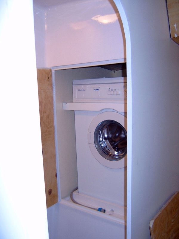
The inside of the showers are now finished. First some layers of epoxi with one layer of glass fibre and then white poly urethane paint (same as hull outside). The floor is painted in gray color with anti skid. The forward shower has a hatch that opens into the washing machine compartment.
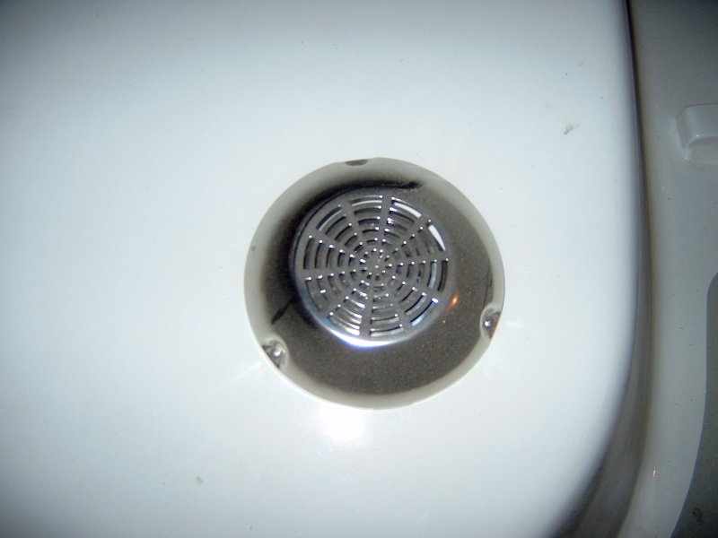
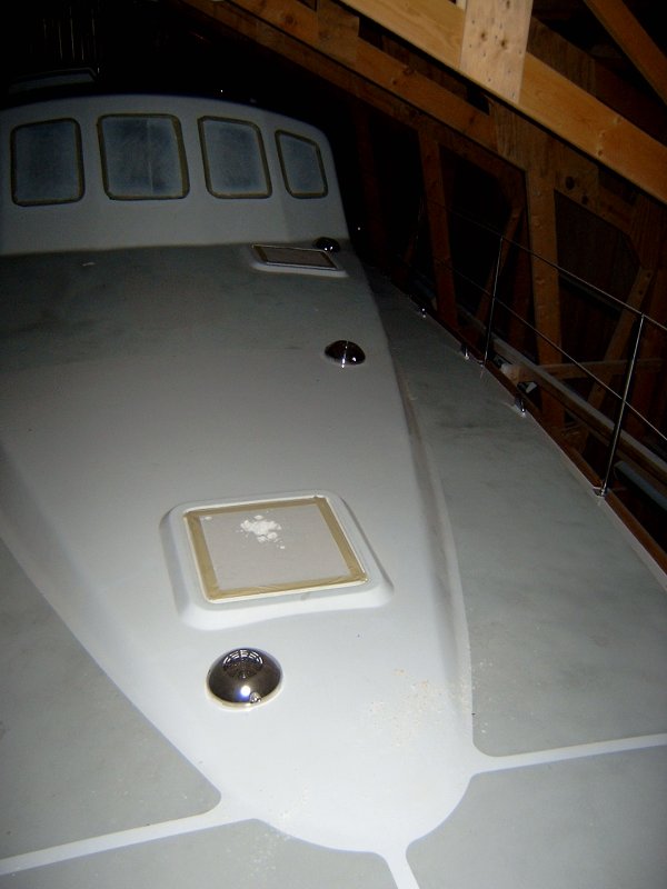
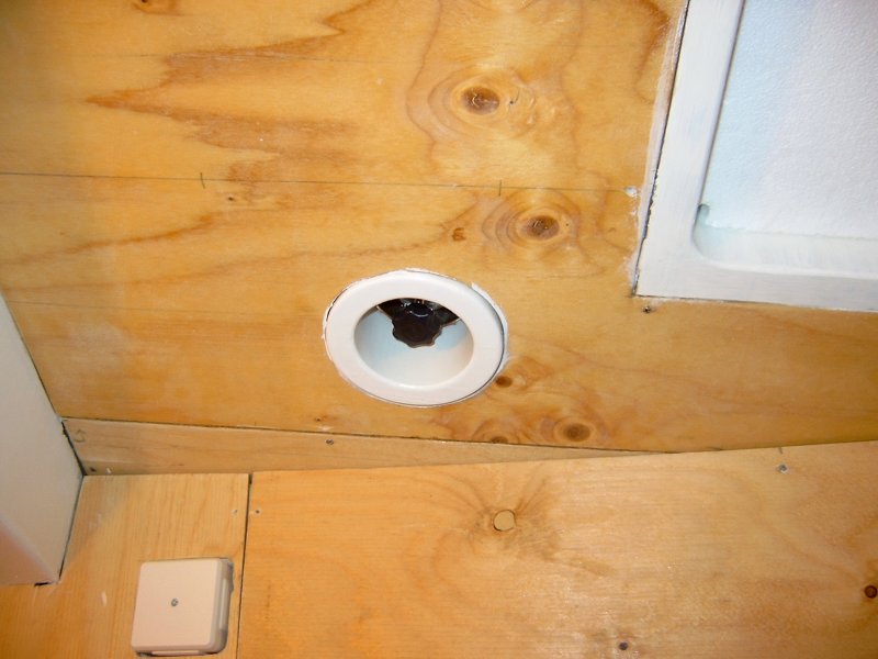
Ventilation of fresh air is another issue. Fresh air needs to come into the boat somewhere, pass through and then get out again. To achieve this I mounted an air outlet ventilator in each cabin and one in each of the two showers. Later I will also add one in the galley. This is what it looks like from the outside. To the left is a close up of one of the ventilators. To the right is a view from inside. Each of the 5 ventilators can be closed from inside in bad weather to prevent salt water from coming into the boat. The ventilators are actually a combination of two different ventilators. The inside is a standard Vetus ventilator and the outside is the top of an Elextrolux ventilator. I chose Vetus for the inside because they are completely stainless and can be closed from inside. A rubber gasket makes them 100% waterproof. The bad thing with the Vetus ventilator is the outside which is not suited for deck mounting where lines will move and get trapped. For this purpose the Elextrolux top is perfect. It's rounded shape adds ejector functionality which increases the effect of ventilation but it also lets lines and ropes pass without getting trapped.
Work with propeller shafts is almost completed. Here is a picture from outside where you see both shafts temporarily mounted. When finished, they will not stick out as much as in the picture and an extra support bearing will be added just in front of the propeller. To the right is another picture from one side. In that picture you also see the ground plate for the HF antenna system.
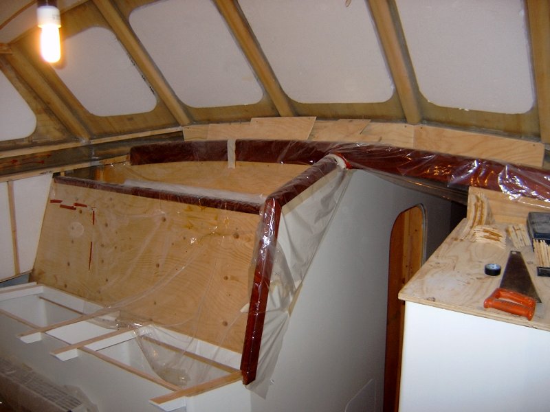
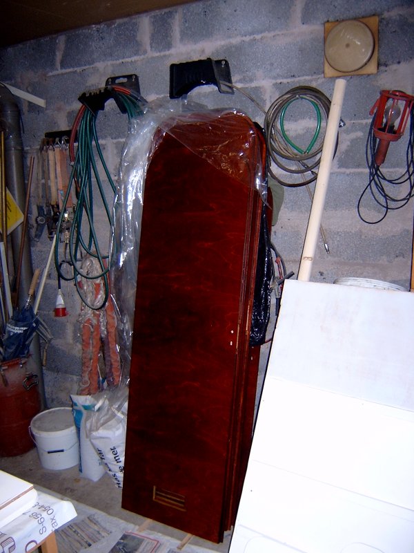
The painting of the interior is more or less finished except for the deck house. White paint is used for almost all surfaces but doors, tables and many details are treated with mahogany stain (bets på svenska) and clear glossy varnish. Above is a picture from the deck house interior and also some other details. The 6 interior doors are finished.
Finally some pictures from some other small jobs:
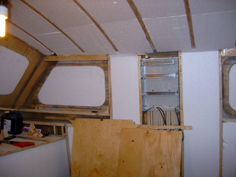
Electric junction box in deck house.
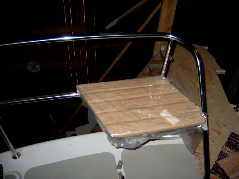
Outside chair on aft deck.
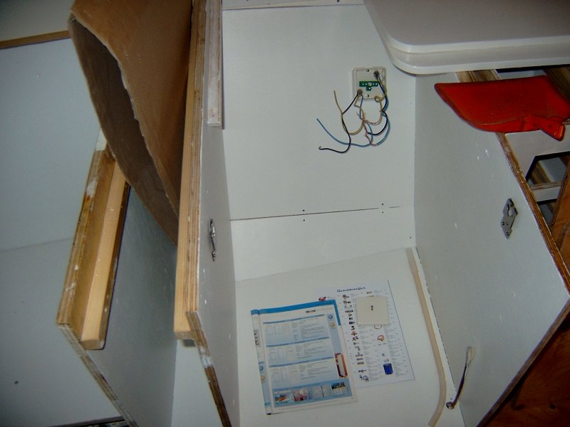
Part of galley with space for gas- and electric stove. For the time being I'm quite exhausted from all this work so I'm now taking a rest for some weeks. I found that playing World of Warcraft with my two sons is a very good way to relax from the boat project and spend time with them. I'm now a level 45 Paldin on the European server Emeriss. Maybe I'll see you ?
October - November
Wet and cold outside but it's warm and dry inside the boat. I have not been working very much last two months. With a project like this you need a holiday now and then. You will never guess what I have been doing, check www.wow-europe.com I'm now a level 60 DPS Pala on Emeriss ! There is not so much left to do with the Bird of Passage, maybe 2 years and starting back in 1998 or something it's close to launching. Many thoughts come up. Selling the farm, moving into the boat, what about the children and the job and so on. The future will tell.
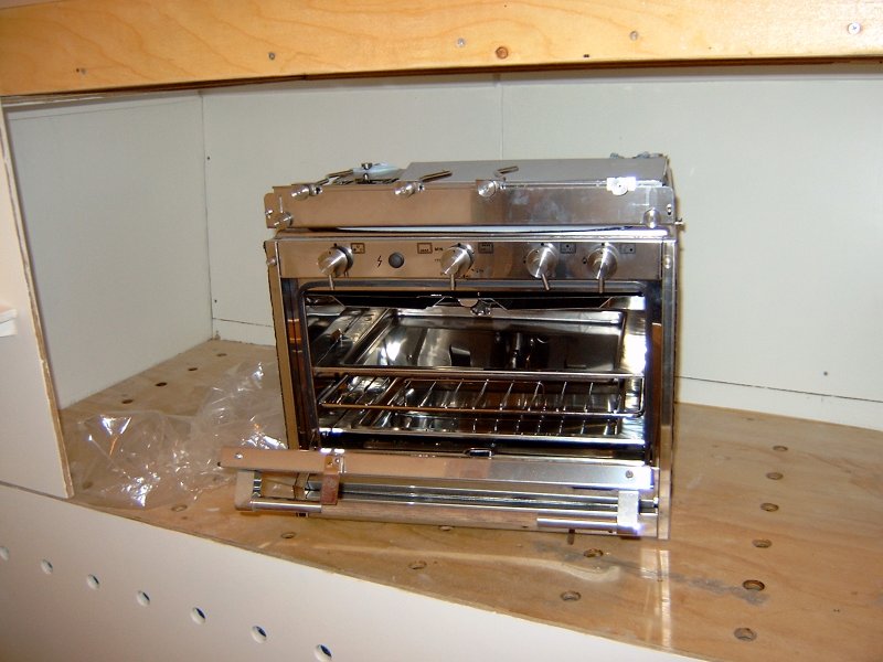
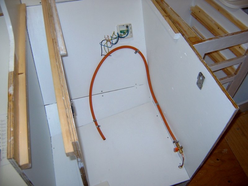
Main jobs this period has been installations. I bought an Italian Techimpex Top Three luxury gas stove and on the right picture above is where it will swing. Everything is stainless. 3 burners and oven with grill. There is room for 2 gas tubes of 6 kg each in one of the aft anchor boxes. I installed an 8 mm copper tube all the way from the anchor box to the galley. The tube is 11 meters long !
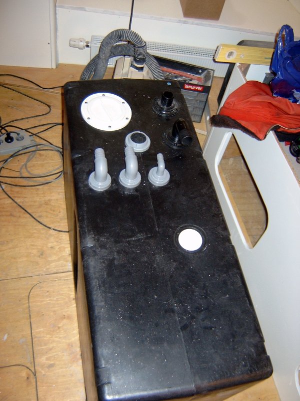
The toilet tank is a big job. Two toilets, showers and sinks. Vacuum suction, emptying with pump to sea, gauge, ventilation etc. Many connections to that tank !
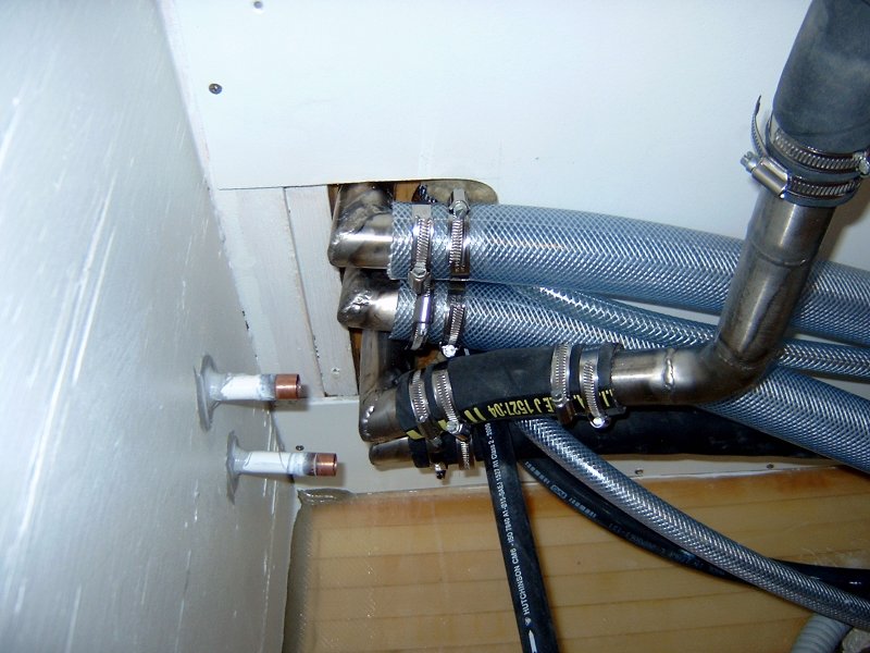
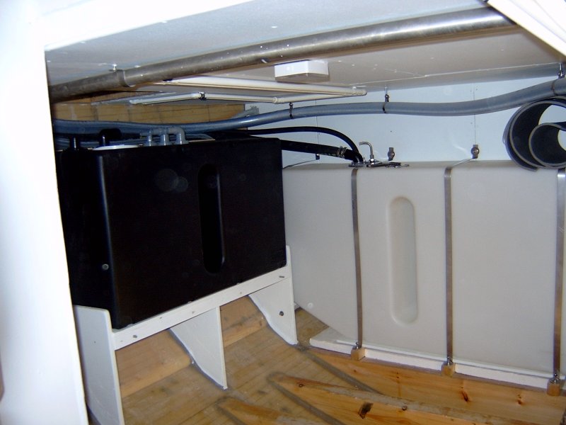
There is actually 5 tanks to connect. Each tank has 4 or more connections and most of them go to the same place. It gets crowded ! The result is nice however, here is a picture from the port machine room. To the left is the 215 liter Vetus toilet tank and to the right is a Vetus 395 liter diesel tank.
